M29C3284
-
Posts
170 -
Joined
-
Last visited
-
Days Won
45
Content Type
Profiles
Forums
Gallery
Blogs
Events
Articles
Store
Downloads
Everything posted by M29C3284
-
I think this picture will answer your question. The top pipe on the filler tube connects to the carburetor air horn. You can also see how the throttle linkage should look like.

-
I'm glad to hear that as I was a bit unsure about the electric fuel pump hose.
-
Glad you liked the parts, I just hope they fit. And on the plus side you got some bubble wrap to play with. Being the purist that I am I would go with spot welding as mush as possible and plug welding where you can't use the spotwelder. This is my spotwelder it's an Wielander Schill InvertaSpot ATM H2O I bought it used very cheap as it was not approved for use on modern car because they changed the steel composition in new cars a few years back and this welder could not weld that type of steel properly. It's a 400 Volt water cooled machine and It's one of the best investment I ever made. What I have learned after doing "a lot" of spot welding is that to get good welds with the standard hand held spotwelder, is to not have the tips to pointy. They need to have a flat of around 3,5-4,5 mm and when you weld you need to be quick and put the right amount of pressure on the tips. I know this can be difficult when using long arms. And if you hold the weld for too long it will only overheat the metal and you end up with brittle welds. When doing a lot of weld you need to watch the temperature of the arms, the quality of the weld goes down when the temperature goes up.
- 356 replies
-
- 1
-

-
- restoration thread
- hull & sheet metal
- (and 2 more)
-
A fortune well spent there Just sent my order to the museum for the same drawing. I can confirm that the T24 and M29/M29C are identical expect the hat channel, the side skirts and a few holes.
- 356 replies
-
- 1
-
-
- restoration thread
- hull & sheet metal
- (and 2 more)
-
This is how the oil seal with housing, that Patrick is talking about, looks like. The picture is showing it from the backside. You should be able to pry it off.
-
Just PM me your shipping details and will get you a quote on the total and payment details.
-
My latest weasel. It's a Swedish Bandvagn m/48 so it only has the hull tag the rest are replaced by Swedish plates. The engine install is T24-9403. I know that this is not the original engine as the Swedish army registration card from 1950 that I have lists T24-11843 as the installed engine. Does anybody know if that was the original engine installed by Studebaker? Also does anybody know which ord. serial this weasel should have?
-
@Patrick Tipton Well you certainly have.😊 You know that there is about double the amount of spot welds on the T24 then there is on the M29C.
- 356 replies
-
- 2
-

-
-
- restoration thread
- hull & sheet metal
- (and 2 more)
-
Nice work as always👍 Do you have any dimensions on the seal installation tool? I would like to make one as well.
-
Thanks Patrick, that is some great advice. I will have to try a slapper as I think I'm stretching instead of planishing with just the hammer. The off dolly technique is one that I really like. I have been playing around with who tight up against the metal I'm holding the dolly. Holding it with a small air gap really works well for me when I don't want to stretch the metal to much. I guess I will just have to keep working at it.
-
After spending a half a day grinding welds I decided I needed to do something else, so I tackle one of does small projects. I only had one good top bow corner pocket so I decided I would try and make one. This was really a good job for the Pullmax. We picked up this P9 a few years ago for next to nothing. The steel it's made off costs more. For those that don't know what a Pullmax is used for, it is used for either cutting or forming. In the case of the P9 model it can cut up to 10 mm mild steel and form up to 6 mm mild steel. It uses a reciprocating upper die and a stationary lower one to form or cut. What make a Pullmax so versatile is that you can make your own dies and form almost any shape. The dies I'm using for this project are plasma cut from 6 mm steel. Then it's just a matter of running your material, in this case 2 mm steel, thru the dies while progressively lowering the top die until you have the shape you want. This is the shaped piece. I always use a bigger piece then the final part, as there will always be some errors at the start. Finished part after cutting to size, drilling holes and bottom cap installed. I plunge milled the 5/16" holes with a endmill because a regular drill would not track straight. Reproduction part next to usable original part.
-
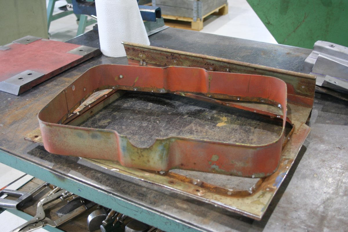
I reached a milestone on my weasel last week when I finished the last of the major sheet metal jobs, so now the hull is complete, just the rest to go. I was thinking about replacing the front top panel, but after seeing Patrick's work on his T24 i decided that I would try straightening it instead. The panel was quite distorted, especially around the fuel filler opening which had been welded shut. I had to remove the reinforcement ring and straighten it first before I could work on panel itself. After an hour or two with the hammer and dolly, oxy/acetylene and shrinking disc I got the panel fairly straight, but I will have to do some lead work to get it where I want it. That will happen after I have sandblasted the whole hull. This was the first time I actually tried straightening a big panel like this, and I could only get it to the point where I could still feel some slight waves in the panel. Any further shrinking did not seam to help getting them to flatten out. I also tired stretching and then re shrinking but it did not help either, I only ended up at the same slight waves I started with. Being in uncharted territory I did not want to beat the panel too much, making it thinner, so I stopped there. Anybody got any tips and tricks on how to get it completely flat? Anyhow the last pieces to "complete" hull was then installed. A big thanks to John for supplying me with the coaming all those years ago. I now finally got to use it. Now it's just all the little jobs left. Grinding weld, straightening the odd dent, welding up unwanted holes, re drilling holes that should be there, well the list is quite long.....
-
Just checked TM 9-772 and yes it must be for the defroster cable. See figure 18 on page 30 in the 1945 edition and figures 17-19 on pages 22-24 in the 1944 edition.
-
Interesting, do you know what that clip is for? Could it be for the windshield defroster cable?
-
@Patrick TiptonAre going to reinstall the tabs for the insulation, or leave those for later after you have primed the hull?
- 356 replies
-
- 1
-
-
- restoration thread
- hull & sheet metal
- (and 2 more)
-
@OZM29CIt's correct the way you have it in the picture. The idler wheel should be facing the back, and the grease fitting should also point to the rear.
-
@F.Janssen I think that the manifold should be black and the grey you found is just overspray. At the factory the engines where assembled with all the accessories and then painted grey, so all the accessories that where already black got overspray on them. As you can see in the picture below. I did not do that when I restored my engine, as I think it doesn't look that good.
-
Nice work. Kinda strange that a simple thing as the windshield assembly is one of the most expensive parts of the weasel.
-
@F.JanssenIs your engine only green or is it grey under the green paint? I know that the Swedish army painted there weasel engines green. @Jim GilmoreThe Swedish army had several weasels with engines where the engine serial did have the T24- prefix also. BTW did you get the email I sent you four weeks ago?
-
You could also just use two pieces of sheet metal of the same gauge, some masking tape and a vice or shop press to make the jogs. Just mark where the jog ends on both sides of the part then tape one piece on each side of your mark and opposite sides of the part, put in the vice or press and squeeze. If should then look something like the part in the picture below. With this method there is no limited to how long you can make the jog.
- 356 replies
-
- 2
-

-
-
- restoration thread
- hull & sheet metal
- (and 2 more)
-
Yes
-
Rats are never fun. Have you checked your planetary gear bushings? Mine where all worn out and I'm still looking for replacements.
-
Thanking the wrong guy, I'm not John But you are welcome anyway.
-
Patrik, I just watched your latest episode and seeing you drilling in the hat channels, I just wanted to give you a tip on how to get round holes in sheet metal. I have found that useing a stepdrill, I think that is what it's called, and a wood backing really helps in getting nice round hole instead of trilobed ones that you always get with a regular drill bit. Keep up the good work.
- 356 replies
-
- 1
-
-
- restoration thread
- hull & sheet metal
- (and 2 more)
-
The 1944 edition of ORD 9 specifies a 24 tooth gear but in the 1953 edition, the one from Portrayal press, the 24 has been crossed out and 25 entered instead. This gear, 197376, is also used in the 1939 and 1940 Studebaker Champion cars, but in the parts catalog for those the tooth count is not mentioned. So I checked one of the two T84J's I have, and it also has a 25 tooth low and reverse gear. It is not NOS so the gear could have been changed. I also have a NOS/very lightly used T84J, that had never been taken apart before I restored it, that I can also check but unfortunately I can't get to it right now. From comparing the G503 and the G179 transmissions I have found that at least these parts are interchangeable: 194264 - Thrust washer 903406 - Thrust washer 903407 - Thrust washer 513002 - Countershaft 513003 - Plate 900889 - Cluster gear bushing 512990 - Roller 512998 - Shaft reverse idler gear 903405 - Reverse idler gear 900899 - Synchronizer assembly