

M29C3284
-
Posts
170 -
Joined
-
Last visited
-
Days Won
45
Content Type
Profiles
Forums
Gallery
Blogs
Events
Articles
Store
Downloads
Posts posted by M29C3284
-
-
@RAS1Thank you.
Since this part is one of those parts that are originally made from unobtainium. I made one, from some scrap thinwall tubing I had laying around. Dimensions in the drawing below.

I flared the ends by placing the tube piece on the round end of a ball peen hammer and then used another hammer to knock the ball end of the first hammer into the tube, creating the flare. I then repeated the process on the other end, cleaned it and painted it with some cold galvanizing paint which I gave a slight polish after it had dried.
-
 2
2
-
-
@RAS1 The round one is correct for the T24, M29 and M29C. The flat tube is for T15 and Studebaker cars from 1932.
-
1
-
-
@RAS1It's 1/2" thick.
-
@M29DeBella jeep parts got NOS coils for the weasel: http://www.debellajeepparts.com/WEASEL.htm
-
1
-
-
@Patrick TiptonMuch better😃
-
1
-
-
@Patrick Tipton Don't forget to add the footman loop next to the front bow pockets before you paint the hull.
-
1
-
-
I'm no expert on norwegian weasels, but your engine have been overhauled by them. I can't say if your weasel is a norwegian return or not from the picture. Does it have a trailer socket.
-
The holes you are showing in the two first pictures should not be there. As for the four rivets on the bottom, they hold the bracket to which the electric fuel pump is mounted to. I would replace the rivets with new ones if they are leaking. They where originally soldered over after installation to seal any leaks.
-
12 hours ago, Patrick Tipton said:
One theory is that the Bakelite paint was applied by brush at the same time they applied the black camo. That color picture you have is the clearest example of "yellow"....otherwise the bottom of all of the T24's in service I see are enough in the shadow that I am not sure....I am going to have to make a choice soon!
I think you are right about that @Patrick Tipton. My T24 (Hull no. 197) still have a few spots of the bakelite paint left on the bottom. And from what I can remember from when I last had a look at it, it looks like it was brushed on.
-
On 5/24/2021 at 2:42 PM, M29 said:
Hi Alexander
That is a nice unit. How much of the weasel hull can you reach? I am looking at an older Hirane auto spotter 140. I have included a picture. it has a long reach tong that I thought would be good for reaching some of the harder to reach areas of the weasel body. I think it has air cooled tips. I know some are water cooled. Any thoughts are appreciated.
Dan
@M29By installing the hat channels and floors before the sides, I managed, with the longest arms, to reach almost everywhere I needed. The only place I could not reach with the was in the front upper corner on the drivers side side panel.
I also sprayed all the areas that where going to be welded with weldable primer and my spot welder handled it perfectly. The areas that where not going to be welded, inside of the hat channels, etc., got two coats of epoxy primer and one coat of Ardrox AV100D. AV100 is a cavity wax.
-
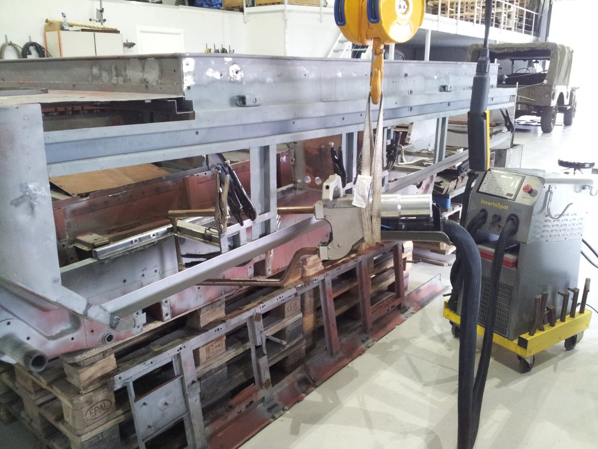
This is the spot welder I use.
It's an Wieländer+Shill InvertaSpot ATM H2O. It's water cooled and has electronic weld time, amp control and clamping pressure so setting it up is very easy. You just choose which type of handle to use; single side/stud gun or the pinch, double side, handle. Set the type of steel; plain, coated or stainless. And then just choose the thickness of the material you like to weld. Like all welding the cleaner the metal is the better the weld will be, even with this machine.
I bought this machine second hand and luckily it came with lots of extra arms and accessories. But I mostly use the longest arms which have a reach of about 60 cm.
One slight nuisance with the InvetraSpot is that the cable between the machine and the handle is very heavy. So using it for longer periods of time is exhausting, that is why it is hanging in the crane☺️
I also have the type that John has. I use it when I need to just do one or two spots. The only problem with that one, is like John says, you have to wait for the electrode tips to cool between welds. Otherwise it is very easy to overheat the electrodes and get brittle welds.
-
16 hours ago, Patrick Tipton said:
Ha! You busted me! YEP 🙂 Had to push it off and redo. Good eyes my friend!😅
By the way, I took a flyer on a coupe of NOS Studebaker water pump rebuild kits for a 40's truck....same as our Weasel. I paid far less than what is currently being charged for the NOS Weasel impellers...and it came with the impeller, shaft and seals 🙂
Not so good eyes actually, more been there done that😄
That is good to know. I think Studebaker used leftover weasel parts in their M series trucks.
-
1
-
-
Nice work, one step closer each day.
Just watched your latest video and noticed something. Did you forget to install the long bolt on the water pump before you pressed on the pulley?
-
7 hours ago, M29 said:
around. 14999: (Planned, but not executed)
Track tension spring design is changed from leaf spring to coil spring.
I thought I would post some pictures of a weasel with possibly the coil spring modification
Dan
That arrangement looks a bit home made, the factory setup is described in the 1945 edition of TM 9-772.
-
17 hours ago, Will Dodge said:
Was the handbrake one that locked around the drive line?
Yes, it is described in the 1945 edition of TM 9-772.
-
Found another change.
14229:
- Reinforcement rings are now installed on the drive wheels.
I have have added this change to the first post.
-
1
-
Thanks, @Patrick Tipton I have now added the correction and new data from my post from yesterday into the list in the first post.
-
@Patrick Tipton I can edit my post a few minutes after I have posted it, but I can't edit after that. I'm only allowed to share or report the post.
-
Thanks, @Patrick Tipton BTW, is there a way that I can edit my first post when new information is found?
I have done some more research and found these changes:
2102:
- Grease fittings are now installed in the guide wheels.
So the change at 5478 is incorrect.
5476:
- Grease fittings are now installed in the drive wheel hubs.
-
I have gone through all the parts catalogs, TM's and articles about the weasel and compiled a list of all the production changes that I could find. The list is by no means a conclusive list of all the changes that happened during the weasel production run, so I would very much like people the chime in if you have anything to add or if you find any errors in my list. The one that are in red text are the ones that I'm unsure about and would like to have confirmed.
I hope this list will be useful to anybody restoring a weasel to factory specs.
All production changes follow the ordnance serial number, found on the data plate behind the driver seat, and all changes came into effect on the serial number after the one stated in the list.
807:
- Oil seals instead of just gaskets are now installed on the drive sprocket shafts.
1002:
- The heater switch is no longer installed.
- The ignition switch is changed to a three position switch.
- The radiator is changed to one with large capacity.
- The fan shroud is changed
- The fuel filter is moved from the front coaming next to the fuel tank to in front of the radiator on the right hand side.
- Grease fittings are installed for lubrication of the bogie wheel shafts.
- Shims are now installed on the bogie wheel shafts to aid in setting bearing pre load.
- The engine compartment divider panel is changed to a two piece design.
- A canvas seal is installed around the gear shift shafts in the engine compartment side panel.
- The radio terminal box changes location.
- The radio antenna cable on the left side of the hull is no longer installed.
- Name change from T24 to M29.
2102:
- Track deisgn is changed, 20" tracks are installed.
- Track skirts are now installed.
- The pintle hook is changed to none swiveling type.
- An H plate is installed on the gear shift lever assembly.
- A guide bracket is installed on the engine for the gear shift rods.
- The compass is no longer installed.
- The voltmeter is no longer installed.
- The hand crank is no longer installed.
- The demolition charge is no longer installed.
- The drivers hand hold is no longer installed.
- The cargo partition is no longer installed.
- The installation of the bogie support arm is changed.
- The bogie wheel yokes change design to being cast instead of shaped from sheet metal.
- The extra rebound bumpers on the two middle traverse springs are no longer installed.
- The design of the traverse springs is changed.
- The idler wheel is changed to a split type design.
- Oilers are installed on steering lever shafts.
- Grease fittings are installed in the guide wheels.
2197:
- The transmission cover gets a breather hole.
2365:
- Change of the safety clip in the clutch.
3102:
- The hand crank hole is no longer installed.
- A transmission service access panel is installed in the rear floor.
- The search light is no longer installed.
- A fixed headlight is now installed.
- The battery is changed from one 12 Volt to two 6 Volt wired in series.
- The location of the fire extinguisher is changed from the back to the front of the vehicle.
- More grease fittings are installed in the bogies.
- The brush guard design is changed, and can no longer be folded down.
- The top back curtain is now a separate piece.
3132:
- All weasels are now painted OD instead of camouflage white and black.
- All canvas parts change colour from white to OD.
3331:
- The radio interference filter on the generator regulator is changed to a condenser.
- The generator to regulator electrical harness is changed to a shielded type.
3449:
- The track tension springs are changed to a 7 leaves design.
- An oil drain plug is now installed in the differential housing on the left side.
3601:
- The fuel pump is changed from a two valve type to a six valve type.
- The air cleaner is change to the oil bath type.
4102:
- Name change from M29 to M29C.
- Flotation tanks are now installed.
- The guide wheel shafts are now replaceable and no longer welded to the guide wheel mounts.
- The canvas seal around the gear shift shafts in the engine compartment panel change colour from white to OD.
- Stretcher brackets are now installed.
4935:
- Lubrication free bushings are now installed in the clutch pedal shaft.
5476:
- Grease fittings are installed in the drive wheel hubs.
8141:
- Seat belts are no longer installed.
9402:
- The text ”LIFT HERE” is now painted next to the lifting holes.
9502:
- The mechanical fuel pump is no longer installed.
- Electric fuel pump installed in the fuel tank is now installed.
- A new tool to check the track tension, by the use of a torque wrench, is now introduced.
10922:
- A warning placard is added about the use of the clutch.
11575:
- An opening is now in cut the left hand radiator support panel to aid in air circulation.
- The design of the canvas seal around the gear shift shafts in the engine compartment side panel is now changed to a metal and felt design.
12325:
- The differential drain plug is changed to magnetic type.
13199:
- The transmission drain plug is changed to a magnetic type.
13560:
- The design of the clutch control linkage is changed.
- Drive wheel carrier brace rods are installed.
- The fuel tank is changed from a metal tank to a self sealing type.
- A ground wire is installed on the electric fuel pump.
14229:
- Reinforcement rings are now installed on the drive wheels.
14682:
- The light switch design is changed to the rotary type.
- Blackout drive light is now installed.
around. 14999: (Planned, but not executed)
- Track tension spring design is changed from leaf spring to coil spring.
15126:
- Weasel production ends, 1945.08.29.
around. 15562: (Planned, but not executed)
- A scraper is installed on the drive wheel carrier to keep dirt and debris out of the drive wheels.
ca. 15681: (Planned, but not executed)
- A handbrake is installed.
-
3
-
Just wanted to through in some information on which track type was used where according to the three Weasel parts catalogs that I have.
Service Parts Catalog for Carrier, Cargo, Light T 24, 1. Aug. 1943
- 905660 – Track, Drive, Assembly
ORD 7-8-9 SNL G-154, G-179, Carrier, Cargo, M28 (T15), M29 (T24) and M29C, 15. June 1944
- 905660 – Track, Drive, Assembly, 15”, low guides, 56 grousers – used to ord. serial. 2102
- 908172 - Track, Drive, Assembly, 20”, high guides, 56 grousers, auxiliary cables – used from ord. serial. 2103
ORD 9 SNL G-179, Carrier, Cargo, M29 and M29C, 9. Feb. 1953
- 905660 – Track, Drive, Assembly, 15”, low guides, 56 grousers – used to ord. serial. 2102
- 908172 - Track, Drive, Assembly, 20”, high guides, 56 grousers, auxiliary cables – used from ord. serial. 2103 to 14108 except 13584, 13585 and 13660 (superseded by 908657)
- 908646 - Track, Drive, Assembly, 20”, high guides, 56 grousers, auxiliary cables – used from ord. serial. 14108 to 14158 except 13584, 13585 and 13660 (superseded by 908657)
- 908657 - Track, Drive, Assembly, 20”, high guides, 55 grousers, auxiliary bands – used from ord. serial. 14159
As you can see the official documentation lists four different tracks, one 15" and three 20" designs. Whether the last design, 908657, was ever install in production or just during post war rebuilds, I don't know.
-
2
-
@Patrick TiptonJust watched your latest video and it looks like your motor is missing the drain tube on the rear main bearing cap.
Also, have you checked the assembly date of you motor? It should be stamped next to cylinder no. 1 exhaust port.
This is my motor, it was assembled 12. March 1945 and the block was cast 6. November 1944 as you can see from the date code.
-
1
-
-
@F.JanssenYou are correct, the cut out should be there. The back panel with the cut out is used for the later weasels that had the stretcher pocket installed from the factory.
This is my very early T24, no stretcher pocket and no cut out.
Just out of interest, does anybody know when they started to install the stretcher pocket?
-
1
-
-
These measurement are from the original Studebaker drawing.
A: 76,2 mm
B: 38,1 mm
C: 6,35 mm
D: 5,1 mm
The angle between A and B is 74 degrees. And the hole for the pivot bolt should be reamed to 9,51-9,53 mm.
Hope this helps.
-
 1
1
-


M29C Weasel - body nr 6672
in Headquarters
Posted
@F.Janssen Very nice.