M29C3284
-
Posts
170 -
Joined
-
Last visited
-
Days Won
45
Content Type
Profiles
Forums
Gallery
Blogs
Events
Articles
Store
Downloads
Everything posted by M29C3284
-
Just checked the drawing and it should be 954381 not 953481, that was a typo on my end, sorry. I have corrected by last post.
-
I think it's avalibale at the Studebaker museum archvie, but I'm not sure as I was given these numbers from a guy thru FB a few years ago.
-
The hull drawing was also something I had been searching for for years. It is not listed in any of the parts catalogs, but I found out that it is only is listed is in an engineering book that lists all parts of the weasel. There is actually two drawings and part numbers you are looking for are: 952800 - Draft - Hull (This is is for the T24 and M29) 954381 - Adaptation - Bow and stern (This is for the M29C) Just do note, both these drawings are on several sheets/rolls and therefore not cheap.
-
@D.R.H.You may also want to look for the assembly date. It is stamped next to cylinder no. 1 exhaust port. This is of my block which was cast 6 Nov. 1944.

-
The exhaust pipe is made from 19 gauge 1-5/8" outer diameter welded tube.
-
The track drive lugs are hardened to Brinell hardness 534-601, so about twice as hard as the drive sprocket teeth.
- 42 replies
-
- 2
-

-
- tracks
- track restoration
- (and 1 more)
-
He will unfortunately not ship anywhere. Which is a bummer because as far as I know he is the only one who makes OEM style bands.
-
@Patrick Tipton I, unfortunately, don't have a seam welder so my plan was to spot weld the sides in a few spots to hold them in place. And then hammer the flange around the tank panel tight. I was then thinking of soldering the joint to fill any gaps. The drawing shows the flange as specified on the original engineering drawing. If that method dosen't work or prove to hard to do. I think I will do it like the drawing below and skip the folded over flange and just TIG weld the side panel and the tank panel to get a leak free edge. I don't want to be a smart ass, but I'm not sure how you will be able to weld the side panels from the inside with the baffles in place.
-
@Patrick Tipton Or at least a shipping container. I plan, if everything goes as planned, to make prototype tank some time later this year. And if it shows that it is not to labour intensive to make a tank, I'm considering making more to order.
-
Not at the moment. But there are plans in motion...☺️
-
When I had my engine rebuilt the rebuild shop that did the machining told me I did not have to install hardened valve seat unless it was necessary. Due to the low compression ratio of these engines and the little use they will see, the wear on the valve seats caused by the unleaded fuel would be negligible.
- 356 replies
-
- 1
-
-
- restoration thread
- hull & sheet metal
- (and 2 more)
-
Next part to make was the hat channel that goes just below the wire edge to stiffen the dash. This was a simple yet tricky part to make. It's made from 1,5 mm (16 guage) steel and it is quite small so I could not bend it in one go in my metal brake. So I made two S shaped pieces which I welded together along the top, then milled the slots and drilled the three holes. The S pieces was tricky to bend as well as the web between the flanges was actually too short to make both bent in the brake so I ended up bending the second flange in the bead roller. If I'm going to make more of these dash panels I'm going to make a tool for the press brake to bend the whole hat channel in one go. Final part to make was the heat duct. Nothing special here, the pictures tells the story😊 Complete dash panel parts kit, except the two wire clamps. Time to start spot welding. I sprayed the inside of the hat channel and the heat duct with high zinc primer before welding it all together. Original and reproduction. The parts left to make is the heat door and the knob for that. Otherwise this project it complete.
-
Like I teased back in September I was going to try and make a new dash panel for my weasel. The reason for this, is like I have already mentioned in a previous post, I don't want to modify an original panel. So I started with drilling and punching all the holes in the main panel, I only spotted these when I cut the panel as my plasma dosen't really cut small holes very well. Next step was the wire edge on the top. I was a bit tricky to fold the metal around the 1/4" tubing I used. In hindsight I should have used a rod instead as the tubing was a bit too soft but it was what I had at hand with the right diameter. Anyway I ended up making multiple bends in the brake and them used the hammer and dolly to close it around the tube. Next task was to form the two pieces that form the channels which the heat door slides in. Here I used my standard method and pressed the step by placing the cut parts between two pieces of sheet metal. The little lip was then just made in the sheet metal brake. There is also a step, dimple (don't really know the English word for it) for the seat bracket on the lower edge that needed to be pressed. Here I just used the same method as before, I just used some heavier gauge metal on the "press tool". The oil servicing door opening has a flange all around the edge. Spawned a few ideas on how to make that and in the end I decided that hammer forming was the best choice here. So I cut two forms from some chipboard and clamped and bolted these to the panel. Then it was only a matter of hammering the flange down little by little. Once I was as close to 90 degrees a possible I removed the forms and did some hammer and dolly work to get some of the kinks out. I will also sand it later to remove some of the worst hammer marks.
-
@42rocker Not at the moment as I have not been able to do much "weasel studying" for the past months. Should you find any yourself, please do post them. @Patrick Tipton Is it possible to make this thread a sticky?
- 19 replies
-
- 2
-
-
- manuals & reference info
- t24
- (and 1 more)
-
@Lighthorse 31Yes, I am. FYI, I just got a new batch of hose fittings in that where a lot cheaper then the last batch, so I have now been able to lower the prices. Please see first post for new prices.
-
@Patrick Tipton Good eyes my friend☺️ Yes I'm making a completely new dash. I have an original one that needs some rust repair, but since this is going to be a bv m/48 I will need to modify it a bit and I don't want to do that to an original dash. So a new one it is.
-
Big thanks to both @Jesse Browning and @OZM29C for posting all these pictures, they will really help me out when I'm going to tackle my tanks.
-
@Patrick Tipton I know the feeling. I too thought that I had gotten all the sand out after blowing, vacuuming and spinning the hull on the rotisserie more times than I can remember. Anyway after the primer had dried I turn the hull upside down and blew out all the hat channels that had any small opening where I could stick the nozzle of the blow gun in, and I got another few kilos of sand out off them. So the next step was to paint all the areas that needed to be OD. I again used a product from the TM-9 range, their synthetic enamel lusterless Olive Drab – Shade #8. I really like this paint as it has good coverage, is dead flat and is very easy to spray. Since this is going to be a Bandvagn m/48, I did not paint the whole hull OD. This is because the refurbishment instructions from the Swedish army, that I have, states that the whole vehicle shall be painted in Swedish army gray no. 076M. But looking at both this hull, before I removed all the paint, and the other m/48 I have it looks like they did not strip out the hull before painting. So I decided to mimic this and paint those areas that are normally covered in OD. I have not put the gray paint on yet as I need to finish all panels and covers first. That is were I'm at right know, but here is a teaser of what's to come.
-
After the tinning was completed it was time for the final sandblast. I did not take any pictures of the finished sandblasted hull as it needed to be primed as soon as possible. Just after getting rid of the ugly red paint, I painted it red again☺️ I thought it would just take a few hours to prime it, but it took me 12 hours to get the hull in primer. There is a lot of nooks and crannies on the inside of the hull that you don't really notice until it's time to paint. I sprayed the inside lower area first, with the hull upside down, and then turned it over on it's side to paint the rest. That I should not have done because then the sand can pouring out from the hat channels☹️ But I could not stop priming so I just tried blowing away as much as possible and continue painting. The sand that got stuck I sanded off ones the primer was dry. The primer I used is the TM9-822 Red oxide epoxy primer sold by Midwest Military. I used 1 us gal. for one complete coat and some touch ups on the areas that where I used filler.
-
@Patrick Tipton Thank you. I learned the hard way about the baking soda trick. Then I used the heat gun to heat the flux so I'm not sure if it I reached to correct temperature to burn off the acid. One downside to using baking soda or any other alkaline solution is if you leave on bare steel it will rust very fast.
-
Time for another update on the restoration. I've been working on getting the hull ready for final sandblasting and painting. And there was few areas that needed more straightening and using the tips I got from @Patrick Tipton I think managed to get close but not perfect. I'm not at his level of expertise when it comes to straightening sheet metal. So I decided I would tin those areas, Patrick have shown the process on his Youtube channel, but I just thought I would just show you the way I do it. It's more or less the same as Patrick, so if somebody missed it here's a repeat☺️ I start off by getting the area to be tinned down to bare metal. I prefer a sandblasted finish because the tinning compound grips the surface better, but a sanded surface works as well. The tinning compound applied. It is used to pre-tin the surface so the tin/lead will stick to the surface. The tinning compound is heated and it has to be brought up to the temperature where the it turns black/brown otherwise the acids in the compound will not be removed. The next step is very important; I spray on baking soda dissolved in water. I use this to removal all the acid form the compound. This is so important because if the acid is not removed completely the metals will start to rust under the tin. Next step is to apply the tin. This is quite easy, on flat surfaces anyway, heat up the tin and the area to be tinned and then just paddle the tin out. The wood paddle is dipped in wax so the tin dosen't stick to the paddle. I used the propan torch on the weasel, but you can also use a heat gun for this step. It is easier to use the heat gun when tinning on vertical surfaces as it is easier control the heat so the tin just dosen't melt off. Last step is to file the tin, I use body files and an orbital sander for this. The tinning on this area turned out OK but I also used some filler on this area, but that came after priming.
-
@Pips_BlaauwI have most of the float tank drawings that are available, and as Patrick points, out they were not cheap. $1000-2000 is what you will have to spent to get them all.
-
Hello Dave Your weasel water pump should fit. You did also remove the water pump adapter from your weasel engine? The parts, that I can think off from the top of my head, that differs between the weasel and the car/truck engine is as follows; Oil pan, bell housing, back plate, distributor, distributor adapter, water pump, water pump adapter and generator mount. The rest of the parts should be the same.
-
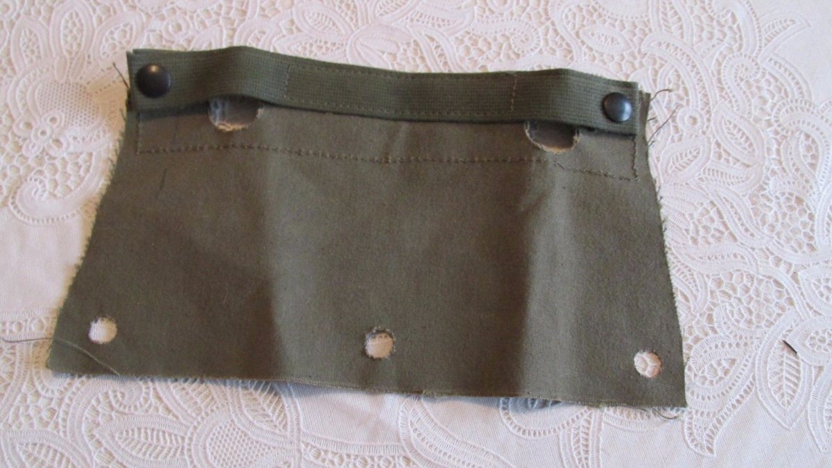
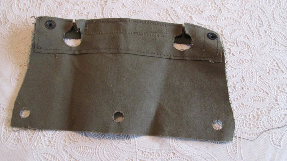
Here are a few pictures of the early canvas shift lever seal, installed from serial 1003. 954165: 954396:
-
@JamesD Thank you. Wow 165 changes that is a lot, we should definitely compare notes. I have checked my notes and the "hot hole" change serial is only mentioned in an old article about the weasel in the club magazine of the Swedish counterpart to the MVPA. I have not been able to confirm it thru any other source. I have also edited my first with your corrections.